

Welcome to ham-interfaces.com
WSJT‑X Setup Guide – FT8 & FT4 Configuration Made Easy
This page aims to give you the basic set-up guide for installing WSJT-X on a Windows Operating system and to ensure your PC Clock is accurately aligned to NTP. It assumes you are reasonably familiar with installing software on your PC and can find your way around Device manager etc.
The setup of JS8Call is very similar so you can use this as a basis but there is no need in JS8Call to have your PC clock set accurately.
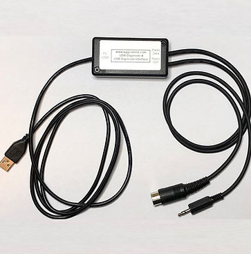
I have based this document around configuring our Digimode-4 interfaces available from our Icom, Kenwood, Xiegu, Yaesu, Alinco and Ten-Tec Shop pages.
Ensuring your PC Clock is aligned to NTP
We need to keep your PCs clock aligned to NTP so that you are synchronised to the transmit/receive time slots in modes such as FT8.
There are numerous applications to which will poll remote NTP server to discipline your PC clock but for simplicity, I would recommend just letting Windows do it for you.
We have created a separate help page here which guides you through setting up Windows Time to accurately keep your PCs clock in check.
Installation of FTDI USB Virtual Comm Port drivers
If you are setting up WSJT-X to use CAT control and you have our Digimode-4 interface, we need to load the USB COMM port drivers.
This is so the PC can control the radios frequency and mode via the CAT port and, if you choose to, use the hardware PTT signal so WSJT-X can put the radio to transmit. It is worth mentioning here that many radios also accept PTT over the CAT commands.
Our recommendation is to use hardware PTT and not CAT PTT. The reason is twofold. Some radios rely on the Data/Accessory port hardware PTT being activated to enable the external audio input and mute the mic.
Also, if your shack is prone to RF pickup, it is feasible that you can get RF interference on the cabling between your PC and transceiver. If you are using PTT via the serial CAT commands the radio will go to transmit but because of the RF pickup, the interface may miss the command to drop back to receive. Using the COM port RTS PTT removes this potential issue.
Our interfaces use the highly reliable FTDI chipset and the drivers may not be native in your OS. At this point, your installation may vary depending on if you are using Windows, MacOS or Linux. I will assume Windows for these instructions.
You can grab the Windows drivers from here: FTDI Drivers
By far the easiest set up (for windows) is to look at the driver entry for Windows (Desktop). In the Comments section on the right hand side is a "Setup Executable". Click on the link to download and install that.
This will download the driver to your Downloads folder. It will begin CDMxxxxx_Setup.zip. Inside the .zop file is a single (safe) executable. Just follow the instruction to complete the installation on your PC.
Connect your Digimode-4 interface to your PC.
Now you can plug your Digimode-4 interface into a free USB port on your PC. You may hear some usual information sounds from Windows as it registers the various devices on the interface. The Digimode-4 has a built-in USB hub to allow both the FTDI Comm port and the built in USB Sound Card to be visible to the PC.
Both the USB Hub chip and the C-Media USB sound card in the Digimode-4 have generic Drivers built into Windows and other OS's.
In the Windows task bar search box, type "Device Manager". From the search pop-up, run the Device Manager application.
First, let's look in the "Sound, Video and game controllers" section. As seen in the image below, you will see a "USB Audio Device" in the list. Remember this name as you will need to select this as your sound card in the WSJT-X audio settings.
Whilst still in Device Manager, let's look in the "Ports (COM & LPT)" section. You should now see a new "USB Serial Port (COMx)". Make a note of this number as you will need it in the WSJT-X CAT settings. In the instance below, my interface inherited COM3.
If you have more than one USB Serial device attached and are unsure which one is the Digimode or CAT interface, unplug it and the devices will refresh. The one that vanished was the one belonging to the interface.

Let's get WSJT-X installed and set up
Download the install WSJT-X
WSJT-X can be downloaded and installed from this link: WSJT-X Download Page
From this installation page you can download the latest releases for your OS. It is available for Windows, MacOS and various flavours of Linux. I will cover the Windows installation here.
Run the downloaded WSJT-X setup .exe file. You will get a pop-up asking if you are happy for the installation to make changes to your device so accept this prompt. The main Setup window will pop up so click on "Next>". At the Licence Agreement page, hit the "I Agree" button. At the next screen accept the system path default option and you can choose if you want WSJT-X as a Desktop Icon. Click on "Next>". The next window allows you to choose the Destination installation folder. I just accept the defaults here and click "Next>". Finally, you can choose if you want WSJT-X to appear in your Start Menu Folder. I just accept the default and at this point click on "Install".
On a modern PC, the installation takes just a few 10s of seconds and when complete prompts you to click "Next>". This completes the installation and you are prompted to "Finish" the installation, and to run
WSJT-X.
Set up WSJT-X
With WSJT-X running, click on the "File" menu option then from the pop-up click on "Settings".
First, we set-up the "General" tab. The important settings here are you enter your Callsign and Grid number. Enter these and press "OK" to store them.

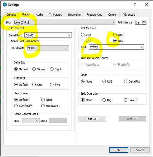
Next we will click on the "Radio" Tab to set up the CAT control. In the example below I am setting up for an Icom IC-718. There are some settings you need to get from your radio and these can be found in the radios built in menu.
If your interface does not have CAT control, you can set the Rig: to "None" in the drop down menu and ignore the settings in the CAT Control section.
- Use the drop-down menu to select the exact Rig: that you have. It is important to pick the correct model of radio here.
- In the CAT Control section, use the drop-down to enter the Serial Port: number. This is the COM port number you noted down from Device Manager.
- Still in the CAT Control section, use the Baud Rate: drop-down to match the CAT speed your radio is set to in its menu.
Now let's look at the PTT Method section. You need to select the appropriate PTT method for your interface. With our Digimode-4 you can select CAT (if your radio supports this) or COM port RTS. We generally recommend using RTS PTT. If your interface does not have CAT control or COM Port RTS keying, set the option to VOX.
- In the PTT Method section, set the Port: number to be the same as the COM port number you noted down from Device Manager.
- Still in the PTT Method section, set the PTT to RTS.
Your settings should look similar to the screen capture below where we have set it up for our IC-718.
You will have noticed two buttons at the bottom of the Radio Tab called "Test CAT" and "Test PTT". Before WSJT-X has checked the CAT settings, "Test PTT" will be greyed out.
If you think all your settings are good, press the "Test CAT" button. WSJT-X will poll the radio and if it reads the frequency OK, the button will turn green (as below) and the Frequency will be updated on the WSJT Status screen.

You will also note that the "Test PTT" is now available. If you have the correct settings in the "PTT Method box" for the COM port number and RTS (or if you have chosen CAT PTT) then try pressing the "Test PTT" button.
If all is OK, the radio transmitter will fire up (with no output power) and the button will turn red as shown below. Pressing the "Test PTT" again will drop back to Rx.


At this point the CAT and PTT settings are complete.
Don't forget to press the "OK" button at the bottom to save the settings.
If you have any of your settings incorrect such as wrong radio type, wrong COM port number, baud rate mismatch, you are plugged into the wrong socket on the radio etc, then you will see the error below. Go back and check the settings match those in the radio and device manager etc.

Next we click on the "Audio" tab to enter the sound card settings. The Digimode-4 interface will be the "USB Audio Device" in the "Intput:" and "Output:" drop-down menus. Choose the sound card as below. You may notice the USB Audio Device is prefixed by a number. Windows does this if it has seen more than one similar device on your PC so that you know which one is which. On the output section, Choose "Both" in the drop-down box. Your settings should look like below for a Digimode-4 interface

Section 5 - Audio Settings and levels
For the Digimode-4 interface, all the transmit and audio levels are set by a combination of level sliders in either Windows or the WSJT-X software.
We will do Receive Audio setup first as it is the easiest.
The first step is to make sure that the USB Audio Device Microphone AGC is disabled. This can cause all sorts of problems with overload and chasing your tail. From the Windows Sound Panel, check the recording properties for the USB Audio Device. In the Custom section, make sure AGC is NOT selected.

Another setting we need to check is the USB Audio Device Microphone "Listen to this device" is NOT checked. If so, this can cause all sorts of issues with feedback.

Tune to an FT8 frequency such as 7.074MHz on 40m. Whilst looking at the USB Audio Device Microphone settings, look in the Levels tab and optimise the level slider such that you put the receive level bar-graph in WSJT-X about mid-range. You can optimise these settings as you become more familiar with the software

Now we will set up the Transmit levels and there are a few things to bear in mind.
The audio level from the interface will set your transmit power. As modes such as FT8 are multi-carrier signals, if you try to generate too much power, you will crush the signals in your radio PA and this will make you more difficult to decode to a remote station. It will also make you very unpopular with adjacent operators as your signal will be so wide you will interfere with their QSO. So the trick is to keep your amplifier nice and linear and out of ALC.
I tend to stick to powers below 40W and this tends to work well. We have written a page on transmit power and ALC optimisation here which you may find useful
From the Sound Control Panel, you can adjust the output level from the USB Audio Device level slider. However, in WSJT-X there is a "Pwr" slider which also adjusts the audio output and hence output power.

You have two options here.
-
Set the level slider in the sound control panel to 100% and then control your power from the "Pwr" slider in WSJT-X main screen.
-
Set the WSJT-X "Pwr" slider to maximum and adjust the the actual power from the level slider in the sound control panel.
My preference is the first option and set my power from the "Pwr" slider in WSJT-X
My last tip on audio levels how to set your power to minimise the risk of over-driving your PA. What I tend to is adjust the output power setting on the radio. Say pick 50% power. Then whilst monitoring the transmit ALC meter, adjust the audio level "Pwr" slider until the ALC is just on the edge of operating. Then back off the audio level by 20%.
If you are running below a power you are happy with, set the output power on the radio up/down and repeat the above step.
These steps should get you a functioning setup with WSJT-X with a clean transmit signal and allow you to start exploring the software and modes.
To fully understand all the features of WSJT-X, I suggest you take a good look at the user guide here: WSJT-X User Guide
There is an operating etiquette and syntax to adhere to with modes such as FT8. It is designed to get the absolute minimum of data across for a QSO and so certain common phrases are pre-coded into the FT8 data structure.
I would spend some hours just monitoring FT8 signals to get the hang of how QSOs operate.